Thermal Subsystem
Table of Content
- Inroduction
- Modes of Heat Transfer
- Low earth Orbit Environment
- Thermal Energy Balance
- Satellite Thermal control
- Conclusion
- Thermal Subsystem Overview
- References
Introduction
For a mission to succeed, spacecraft temperature control is essential. To keep the spacecraft and its compo- nents within a temperature range, thermal control for a spacecraft requires controlling the energy entering and leaving the spacecraft. The thermal design ensures that the specified values of any spacecraft in the orbit are not exceeded.
Modes of Heat Transfer
There are three modes of heat transfer including radiation, conduction, and convection. Generally, heat transfer in a satellite occurs due to radiation and conduction, which account for the heat exchange between the components inside the satellite in a vacuum. Radiation is the only means of heat rejection from the satellite into space and heat transfer from celestial bodies to the satellite. The satellite will encounter convection on the ground, during ascent [2].
Radiation
The radiation emission depends on the emissivity ϵ, the surface area A in m2, the Stefan-Boltzmann constant σ, and the temperature T in K. The subscript “e” denotes radiation emission. The Stefan-Boltzmann
constant is 5.67 × 10⁻⁸W/m2 ·K 4. The flow of energy per unit area per unit time is heat flux q, where Q˙ and Q denote the rate of heat flux and the total amount of heat transferred respectively.
qe = σT4
Q˙e = ϵAσT4
Conduction
According to Fourier’s law, conduction is caused by the temperature gradient through a solid material. Con- ductivity depends on material temperature, but it generally remains constant in the range of temperatures that satellites encounter.

Convection
In satellite thermal analysis, convection will take place during ground operations and ascent.
Low Earth Orbit Environment
A satellite in low Earth orbit (LEO) is located between 150 km and 1000 km in altitude. the only external sources of heat that a satellite will be subjected to are direct solar radiation, Earth albedo radiation, and Earth infrared radiation. Effects from other celestial bodies, from elementary particle bombardment, and from space background are assumed to be negligible [2].

Figure 1: Orbit β angle [3].
β is the minimum angle between the orbit plane and the solar vector and can vary from −90◦ to +90◦. If the satellite is moving around its orbit counterclockwise, as seen from the Sun, the beta angle is positive; if clockwise, it is negative.
Direct solar radiation
Direct solar radiation, absorbed by a surface depends upon the solar absorptivity α of the surface, the solar constant S, and the incident angle θ from the surface normal to the solar vector. The amount of direct solar radiation that is absorbed by a surface relies on the solar absorptivity α of the surface, the solar constant S, and the incident angle θ from the surface normal to the solar vector.
qsolar = αS cosθ
This fall to zero inside the eclipse zone and reaches to a high value depending on the surface area of the satellite. For 3U CubeSat it can reach approximately 25W [1].
Albedo radiation
The solar energy reflected off the Earth is referred to as “albedo radiation”. It is a function of the orientation of spacecraft in the orbit and when the spacecraft is near the Earth, it can be a significant source of radiation. The heat flux caused by albedo that strikes a surface of satellite depends on the surface absorptivity α, the solar constant S, the albedo factor Af , and the view factor F between the surface and the Earth. Surfaces facing away from the Earth will receive no heat flux due to albedo.
qalbedo = αSAfF
The albedo factor is dependent upon the surface properties of the Earth. Different reflection values of clouds, water, ice, land, and woods will lead to different albedo factors. Typically, the albedo factor for clouds is around 0.8, whereas the factor for fields and forests can range from 0.03 to 0.3.
For the analysis of the satellites, the albedo factor can be considered as a constant between 0.25 and 0.35. This fall to zero inside the eclipse zone and reaches to a value depending on the surface area of the satellite. For 3U CubeSat it reaches to approximately 8W [1].
Earth IR
The Earth absorbs all incident solar radiation that is not reflected by its surface as albedo and emits it again as long-wave infrared radiation. The amount of IR energy absorbed by a satellite from the Earth depends on both its direction in relation to the earth and its temperature.
qIR = σϵFTE4
Different faces of the satellite have different values of absorbed IR energy. For 3U CubeSat, the total infrared radiation absorbed is approximately 2W [1].
Spacecraft heat generation
For non-moving parts of satellite, the electrical-power draw for components will be converted entirely to heat. The total amount of heat produced by a satellite will then depend only on the power consumption of the components. During the mission, heat dissipation of components may vary around the orbit due to the requirements of different mission phases.
Spacecraft Radiation emission
Radiation emission encompasses a diverse range of electromagnetic radiation types that are emitted. This includes radio waves for communication, visible and infrared light for Earth observation, and signals for navigation (e.g., GPS). The magnitude of radiation emissions is governed by the available surface area and its optical characteristics.
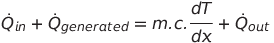
Thermal Energy Balance
The thermal management of a satellite in orbit typically involves the equilibrium between the energy acquired from its surroundings and the internally generated energy, with the energy stored and emitted by the satellite in the form of radiation, in accordance with the principle of energy conservation. The stored energy can be represented in terms of specific heat which is a property of the material and it varies for different materials that are used in the satellite. It should be noted that the effects of conduction are not taken into consideration in this energy balance.

For example, the total absorbed heat power from external sources for 3U CubeSat is ranges from approxi- mately 2W to 35W depending on the current position of the body.
Satellite Thermal Control
Numerous satellite thermal management systems employ a blend of passive and active control mechanisms. Passive control techniques constitute the predominant portion of the system, while active control methods serve as additional measures for equipment with limited temperature tolerances. Passive control methods are the preferred choice for small satellites like Cubesats, although they may require increased surface area or support from deployable systems to effectively dissipate heat from the satellite.
Active Thermal Control
Active thermal control relies on mechanical or electrical systems to regulate temperatures within speci- fied ranges. These systems need a power source and may include moving parts, making them less reliable compared to passive thermal control methods. Therefore, active systems are employed only when simpler temperature control methods are not sufficient. Some examples of these are devices are Heaters, Thermo- electric coolers.
CubeSats typically avoid active thermal control due to power constraints, size limitations, and cost con- siderations. These small satellites have strict power budgets, and active systems demand constant energy, limiting the power available for other critical functions. Additionally, CubeSats prioritize simplicity and reliability, making complex active systems with moving parts less attractive.
However, some CubeSat missions with specific thermal management needs may incorporate limited active systems. For example, Heaters can be used to actively warm certain components or systems when necessary, particularly in missions with extreme temperature variations.
Passive Thermal Control
To keep temperatures within acceptable ranges, passive thermal management approaches include material property selection, managing the flow of heat transfer, and using insulating systems.
Passive techniques are most frequently used by small satellites since they are typically lighter, more reliable, and power-free. Multilayer insulation, thermal surface coatings and finishes, tapes, radiators, heat pipes, phase change materials, louvers and heat switches are examples of passive thermal management techniques.
Insulation
Thermal insulation repels radiation and prevents the unnecessary dissipation of heat. The widely favored type of insulation is MLI blankets, where heat transfer involves a combination of conduction and radiation. Utilizing as many sheet layers as feasible reduces the radiation heat transmission. By selecting low-density materials for the spacers and making sure that the embossing on the sheets is sufficient to reduce contact between the layers, conduction heat transfer is reduced.
CubeSats, being smaller satellite systems, generally do not incorporate insulation, notably Multi-Layer Insulation (MLI). The primary constraint in applying insulation lies in the limited available space, as not all CubeSats are equipped with deployable solar panels,leaving insufficient surface area for applying MLI or any other form of insulation.
Surface coatings and finishes
The emission and absorption of energy from surfaces can be controlled. Almost any combination of absorp- tivity and emissivity has been generated in a broad variety of materials, coatings, and paints that can be utilised for temperature management.
Common surface treatments
A satellite has thermal control surface finishes on almost all of its interior and exterior surfaces. Although there are many other hues of space-qualified paints, black and white are the most frequently utilised ones. The outside layer of insulating blankets, radiator coatings, and paints are examples of external surfaces.
Tapes
Thermal control tapes in CubeSats primarily function to provide insulation, protect components from ex- treme temperatures, and secure thermal materials in place. They help maintain stable internal temperatures by preventing excessive heat transfer and offer shielding from harsh space conditions, ensuring the satellite operates effectively. When low emittance is desired, aluminium or gold-coated tapes can be utilized. Before applying tapes, surfaces should be clean and oil-free to guarantee strong adhesion.
Radiators
Radiators are used to reject waste satellite heat into space. Most radiators feature low absorptivity to reduce heat loads from the surrounding environment and high emissivity to maximise heat rejection. Both heat impinging on the satellite and waste heat from the satellite must be rejected by radiators.
Tapes can function as radiators in CubeSats. However, if considering a dedicated radiator, it necessitates a heat transportation system to move excess heat. CubeSats, due to their limited space and dominant solar panel coverage, pose challenges for accommodating dedicated radiators.
Conclusion
For spacecraft to perform well throughout missions, proper temperature analysis and control are necessary. The results of the thermal analysis are influenced by the solar vector, albedo variables, satellite component dissipation, orbit beta angle, and orbit altitude. The range of different radiations is given for a 3U CubeSat from the literature.
For the thermal analysis of a satellite, coordination among various subsystem experts is essential. The indi- vidual responsible for thermal analysis should collaborate with the Electrical Power System (EPS) specialist to ascertain the satellite’s power requirements. Information about the satellite’s orientation must be pro- vided by the Attitude Determination and Control System (ADCS) specialist. Subsequently, in conjunction with the Structural subsystem expert, a thermal model is developed. This model is then subjected to sim- ulation using thermal software to predict the satellite’s behavior in the vacuum environment under specific conditions.
Thermal subsystem overview
The thermal subsystem is responsible for overseeing the temperatures of satellite components during the mission, using temperature sensors. Its main objective is to keep these temperatures within specified ranges. To achieve this, a thermal model of the satellite is constructed, and various methods are applied to control and manage the satellite’s temperature effectively.
Thermal desktop software serves the purpose of developing the thermal model of the satellite and subse- quently conducting simulations under defined conditions within a specific orbit. While alternative software such as Ansys may be employed for various simulations, it is noteworthy that Thermal desktop stands out for its superior accuracy compared to Ansys.
| Subsystem | T◦min[ ◦C] | T◦max[ ◦C] |
|---|---|---|
| Batteries | 0 | 25 |
| ADCS | -40 | 85 |
| OBC | -40 | 85 |
| EPS | -40 | 85 |
| VHF-UHF antenna | -40 | 85 |
| S-Band antenna | -40 | 85 |
| Solar panels | -100 | 100 |
| Main structure | -40 | 85 |
Table 1: Operating minimum and maximum temperature values (Tmin◦ and Tmax◦ , respectively) for the satellite subsystems [1].